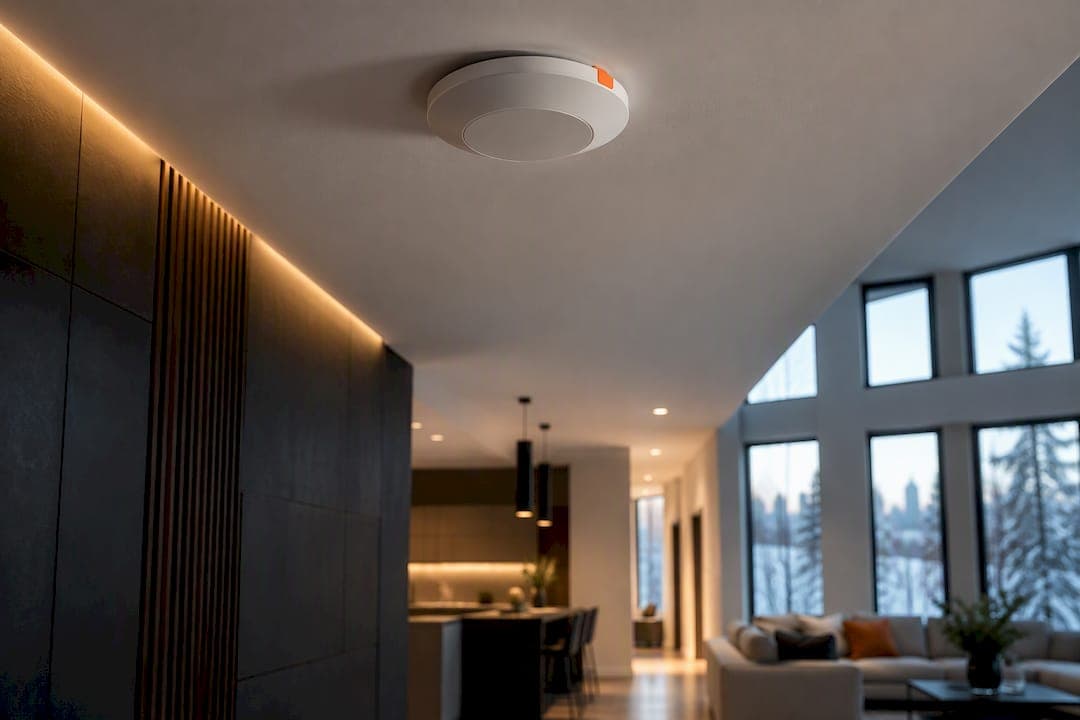
Put access points centrally and up high, use wired backhaul where you can, and avoid more than two interior walls between the access point and the devices you care about. Watch for two things once you do this: crowding too many radios into one area causes interference, and dense construction or a large floor plan may still need more than one access point. Run a short walk-through and a basic scan before buying anything else.
TL;DR:
- Placing access points within two rooms of devices and centrally located significantly reduces dead zones in home Wi-Fi networks.
- Ceiling mounting on or above head height improves coverage by avoiding signal attenuation caused by furniture, bodies, or appliances.
- Using wired Ethernet for backhaul enhances overall speed and reduces latency compared to wireless relay methods, especially under heavy load.
- Proper channel planning on 2.4 GHz and 5 GHz bands prevents interference, with some setups benefiting from disabling 2.4 GHz entirely in crowded environments.
- Professional site surveys, on-site testing, and structured wiring significantly improve Wi-Fi coverage, especially in larger or multi-floor buildings, minimizing the need for multiple access points.
Table of Contents
- Core placement rules and a quick checklist you can use immediately
- Mounting and height: why ceiling mounting usually wins
- Interference and channel planning: reducing CCI and ACI
- Backhaul and cabling: why Ethernet still wins
- Capacity and density: how many access points do you actually need
- Predictive site surveys and why on-site testing still matters
- Routing around obstacles and special-case installs
- What a professional installer actually delivers
- Fitting new access points into a network you already have
- Why power over Ethernet shapes where you can put an access point
- Placement choices that affect security, not just signal
- Planning access points across multiple floors
- Confirming the install worked: validation and fine-tuning
- Types of access points and how each one changes placement
- When DIY placement is enough and when it isn't
- Getting your access point placement right the first time
- Sources
- FAQ
Core placement rules and a quick checklist you can use immediately
Most home Wi-Fi problems trace back to one thing: the access point sits wherever the internet line happens to enter the house, not where people actually use their devices. Fix the location first and most complaints disappear.
The clearest, most repeatable rules for home placement come from a widely cited field guide from Ars Technica, built around simple counting rather than guesswork.
- Count the walls. Aim for no more than two interior walls or two rooms between the access point and the spots where people actually work, stream or game.
- Centralize, don't default to the closet. Place the access point near the middle of the coverage area, even if that means running a cable somewhere less convenient than the modem's corner.
- Halve the distance when you add capacity. If you are adding a second access point to reach a far room, put it roughly halfway between the first access point and the trouble spot rather than at the far wall.
- Mount it above head height. Furniture, bodies and countertops absorb signal, so anything at or below waist level loses range fast.
- Turn the power down, not up. Maxing out transmit power creates a single oversized, unstable cell instead of several well-behaved ones; a lower, evenly balanced setting improves how devices roam between access points.
Pro Tip: Before adding a second access point, move your existing one to the most central room in the house for a day and see how much the dead zones shrink on their own.
These five rules solve the majority of home coverage complaints without spending another dollar. The Ars Technica guide and vendor documentation from router makers converge on the same basic logic: fewer obstacles, shorter distances, balanced power.
Mounting and height: why ceiling mounting usually wins
Ceiling mounting keeps the access point above the clutter that eats signal, which is why installers default to it whenever the structure allows. Bodies, sofas, filing cabinets and kitchen islands all attenuate a signal that has to pass through or around them, and a ceiling-mounted unit skips most of that entirely.
- Ceiling mounts give a clearer, more even line of sight to devices scattered around a room or open floor plan.
- Wall mounts work well for long hallways, retail aisles or narrow spaces where a ceiling mount would aim signal at the floor and ceiling instead of down the corridor.
- Avoid concealing an access point above a dropped ceiling. According to WatchGuard's deployment guidance, the metal grid and ductwork common in drop ceilings can meaningfully attenuate the signal, undoing the benefit of the height.
- Keep access points away from large metal appliances, refrigerators and electrical panels, which reflect and block radio waves in ways that are hard to predict.
- Point omnidirectional antennas straight down or straight out depending on the mount, since they radiate in a donut pattern around the unit.
- Aim directional antennas at the specific zone needing coverage, such as a warehouse aisle or an outdoor patio, rather than entering them in open space.
Where ceiling access is not an option, a high wall mount, oriented to avoid furniture and pointed toward the busiest part of the room, is a reasonable second choice.
Interference and channel planning: reducing CCI and ACI
Two access points on the same channel compete for airtime, a problem known as co-channel interference, while two access points on channels that overlap but are not identical create adjacent-channel interference, which is often worse because devices cannot properly avoid it. Both waste airtime and slow every device connected nearby.
- On the 2.4 GHz band, stick to channels 1, 6 and 11. Only three non-overlapping channels exist on 2.4 GHz, so any other channel choice guarantees overlap with a neighbour.
- On 5 GHz, take advantage of the much larger channel set, but expect some channels to require dynamic frequency selection, which can briefly pause traffic if radar activity is detected nearby.
- In homes or small offices with several access points close together, consider disabling 2.4 GHz on some units entirely, since vendor guidance notes this reduces self-induced congestion on the more crowded band.
- Run a basic Wi-Fi scanner app before finalizing placement and look for two things: how many networks share your chosen channel, and whether your own access points overlap each other.
A scan that shows five or six neighbouring networks stacked on channel 6 is a clear signal to shift to 1 or 11 rather than fight for space that isn't there.
Backhaul and cabling: why Ethernet still wins
Wired backhaul beats wireless backhaul under real load, full stop. A wireless mesh link has to split its airtime between talking to client devices and relaying traffic back to the router, which cuts available throughput and adds latency exactly when a network is busiest. Ars Technica's testing points to wired Ethernet as the consistently stronger choice wherever running a cable is practical.
- Run Ethernet to every access point you can, even if that means a short conduit run through a basement or attic.
- If wireless backhaul is unavoidable, place the relay node roughly halfway between the main access point and the farthest client, mirroring the same halving rule used for wired expansion.
- Use conduit for any cable run through unfinished space so future changes do not mean opening walls again.
- Plan the pull path before drilling: attics, basements and closets usually offer the shortest, least disruptive route between rooms.
Pro Tip: A single home run of Ethernet to a central ceiling location often solves more coverage problems than two additional mesh nodes.
Homeowners comfortable with a fish tape and a drill can often run a short cable themselves; longer runs, finished walls or multi-floor routing are where hiring an electrician or low-voltage installer starts to pay for itself. A practical Ethernet wiring guide covers the cable types and connector standards worth knowing before starting.
Capacity and density: how many access points do you actually need
A single well-placed access point typically covers an area between roughly 1,000 and 2,000 square feet in a home, with the lower end applying to older construction with plaster walls, brick or dense wiring, and the higher end to open, newer builds with drywall interiors.
- Measure or estimate your usable floor area, then divide by 1,500 square feet as a starting midpoint for typical construction.
- Add an access point for any area separated by more than two walls from the nearest one, per the wall-counting rule.
- For basements, additions or detached structures, treat them as separate zones needing their own coverage rather than stretching one access point to reach them.
- In high-density spaces such as conference rooms, auditoriums or event venues, capacity planning shifts from square footage to users per radio, and Cisco's design guidance for large public venues recommends dedicated RF design work involving antenna selection, cell shaping and strict channel reuse.
A 2,400-square-foot two-storey home with plaster walls on the main floor might need one access point per level rather than one for the whole house, simply because the wall count between floors and rooms adds up quickly. Once a space starts approaching auditorium or warehouse scale, the calculation stops being a square-footage exercise and becomes a professional RF design project.
Predictive site surveys and why on-site testing still matters
A predictive survey uses a scaled floor plan, marked wall materials and an estimate of expected device density to model coverage before a single access point goes up. Vendor best practices recommend feeding this kind of planning software an accurate drawing rather than a rough sketch, since wall material assumptions change the predicted signal loss significantly.
- A good predictive model needs the floor plan drawn to scale, not just labelled rooms.
- Wall and floor materials matter: concrete, brick and metal studs absorb far more signal than drywall and wood framing.
- Expected device density per room changes recommended access point count and channel assignment, not just placement.
- Predictive tools output a coverage map, estimated signal-to-noise ratios by area and suggested channel assignments per access point.
None of that replaces a physical check. Temporary test units placed at the modelled locations, then walked and measured with a phone or laptop, catch real-world surprises such as an unmarked steel beam or a microwave that the floor plan never flagged. Predictive planning narrows down where to start; on-site validation confirms it actually works.
Routing around obstacles and special-case installs
Some obstacles cause more signal loss than a simple wall count predicts. A homeowner's guide to Wi-Fi dead zones flags dense bookshelves, aquariums, mirrors and large metal appliances as common culprits that punch far above their apparent size.
- Concrete slabs and load-bearing masonry walls cause heavier signal loss than the standard drywall assumption behind the two-wall rule.
- HVAC ducts and mechanical chases behave similarly to metal appliances, reflecting and scattering the signal rather than absorbing it cleanly.
- Staggering access points rather than lining them up in a straight row helps route around a single stubborn obstacle instead of pushing signal straight through it.
- Aligning an access point with doorway sightlines, even indirectly, often beats trying to punch a stronger signal through a solid wall.
- Running a short cable to reposition an access point on the far side of a problem obstacle usually beats increasing transmit power to compensate.
In arenas, lecture halls or dense seating areas, under-seat or enclosed access point mounts are sometimes the only workable option, a trade-off documented in Cisco's venue design guidance. These installs trade easy access and cooling for a physically protected, sightline-friendly location, and they need many more access points than an equivalent open space.
What a professional installer actually delivers
A professional installer's process looks different from a DIY placement session mainly in the paperwork and the tools involved. Expect an annotated floor plan marking every access point location, a heatmap showing measured signal strength room by room, and signal-to-noise ratio checks taken at the actual trouble spots rather than estimated from a model.
- Annotated floor plans and heatmaps document what was installed and why, useful for troubleshooting later.
- Post-install tuning adjusts channel assignments and transmit power after the physical install, based on measured rather than predicted results.
- Structured, concealed wiring keeps cable runs out of sight while still delivering wired backhaul to every access point.
Pro Tip: Ask any installer for the heatmap and channel plan in writing before the job is considered finished, not just a verbal "it's working now."
Multi-floor coordination, concealed ceiling mounts and structured wiring through finished walls are the situations where a professional installer earns their fee fastest, since these are the jobs where a wrong guess means opening drywall twice.
Fitting new access points into a network you already have
Adding access points to an existing router setup only works cleanly when every unit shares the same network name, security settings and, ideally, sits on the same VLAN or subnet as the rest of the network. Mismatched settings are a common cause of devices refusing to roam between access points even when signal strength looks fine on paper.
Scalability comes down to planning for growth before it's needed. A single router bought to cover one bedroom rarely becomes a whole-home solution just by adding more of the same unit, since consumer routers often lack the channel planning and roaming controls of dedicated access point systems. Where a household or small business expects to add more devices, more floors or more square footage over time, starting with equipment designed to be managed as a group, rather than as isolated routers, saves a redesign later.
A network switch with enough ports for every wired access point, plus a couple of spares, avoids the need to add a second switch the moment one more access point gets installed. For anyone building out a home network from scratch, a practical guide to smart home networking covers the basics of tying multiple devices and access points into one coherent setup rather than a collection of separate networks.
Why power over Ethernet shapes where you can put an access point
Power over Ethernet lets a single cable carry both data and electrical power to an access point, which matters enormously for placement because it removes the need for a nearby electrical outlet. Without it, every ceiling-mounted or mid-wall location is limited to wherever an outlet happens to already exist, which is rarely the ideal spot for coverage.
A PoE injector or a PoE-capable network switch handles the power delivery, and the standard used affects how much equipment a single cable can support. Some access points, particularly those with multiple radios or built-in features like Bluetooth beacons, draw more power than older PoE standards deliver, so checking the access point's power requirement against the switch or injector's output avoids an underpowered install.
Because PoE removes the outlet constraint, it directly enables the central, elevated placements recommended earlier: a ceiling location in the middle of an open floor plan or hallway is only practical when the same cable delivering data can also deliver power. That single cable run also keeps the finished look clean, without a power cord running along a ceiling or down a wall to the nearest plug.
Placement choices that affect security, not just signal
Where an access point sits affects more than coverage. A unit mounted somewhere clearly visible and easy to reach is also easy to tamper with, unplug or physically swap out, which matters in shared buildings, rental properties or any commercial space with public foot traffic.
Ceiling mounts and recessed placements offer a practical security advantage alongside the signal benefits already covered: they are harder to reach without a ladder, less likely to be bumped or covered by furniture, and less visible to anyone casing a space for equipment worth stealing. In commercial or multi-tenant settings, that visibility question extends to whether an access point sits inside a space the business controls or in a shared hallway or utility room accessible to other tenants.
Beyond physical access, placement also affects how easy it is for someone outside the building to intercept signal. An access point positioned near an exterior wall facing a street or parking lot extends usable range outside the building's own boundary, giving anyone parked nearby a stronger signal to work with. Centralizing placement, the same rule that improves coverage, also naturally reduces how much usable signal reaches outside the property line.
Planning access points across multiple floors
Multi-floor homes and buildings change the placement math because floors themselves count as one of the toughest obstacles a signal can cross. A single access point on the main floor rarely reaches a finished basement or a third-storey bedroom with the same strength it delivers to the room next door, since floor assemblies often contain more material, and more metal, than a typical interior wall.
Rather than stacking access points directly above one another, offsetting them slightly between floors avoids sending two full-strength signals through the same small patch of floor and ceiling, which is a common cause of interference between levels. Each floor is generally better treated as its own coverage zone, following the same two-wall and central-placement rules independently rather than assuming one strong access point will serve the whole structure.

Stairwells and open-concept staircases are useful exceptions, since they often let signal travel between floors far more easily than a solid floor assembly does, and an access point positioned to take advantage of that opening can sometimes cover a partial second zone. Basements deserve their own consideration too: below-grade concrete and earlier construction techniques tend to include denser materials, which is part of why basements are frequently flagged as a placement location to avoid entirely, per TP-Link's home placement advice.
Confirming the install worked: validation and fine-tuning
Placement decisions are only as good as the measurements that confirm them. A basic smartphone Wi-Fi analyzer app shows signal strength and channel usage room by room, which is enough to confirm whether the two-wall rule and central placement actually delivered the coverage expected on paper.
For a more complete picture, a walking heatmap survey, where a laptop or phone logs signal strength continuously while moving through every room, reveals gradual weak spots that a handful of static readings can miss. This is the same output a predictive planning tool produces before installation, now measured against reality rather than modelled.

Post-installation tuning usually means small adjustments rather than a full redo: nudging transmit power down on an access point that is overpowering its neighbours, reassigning a channel that turned out to clash with a neighbour's network, or repositioning a single unit a few feet to clear an obstacle that wasn't obvious until the signal was actually measured. Revisiting this check periodically matters too, since new appliances, renovations or a neighbour's new router can all shift the interference picture months after the original install.
Types of access points and how each one changes placement
Indoor and outdoor access points are built for different placement demands. Outdoor-rated units include weatherproof housings and a wider operating temperature range, which allows placement under eaves, on exterior walls or in covered outdoor living spaces where an indoor unit would fail quickly.
Omnidirectional access points, the type found in most homes, radiate signal outward in a roughly even pattern around the unit, which is why central placement matters so much for them specifically: an omnidirectional antenna near a corner wastes most of its coverage pattern on empty space outside the building. Directional access points instead focus signal into a narrower beam, useful for long hallways, warehouse aisles or point-to-point links between two buildings, but a poor fit for an open room where even coverage matters more than reach in one direction.
The choice between these types shapes where an access point belongs before mounting height or wall count even enters the conversation. An outdoor patio calls for a weatherproof, likely directional unit aimed at the seating area, while an open-concept living space calls for an indoor omnidirectional unit placed as close to the room's centre as the ceiling allows.
When DIY placement is enough and when it isn't
Most home networks improve dramatically from three free moves: centralizing the access point, mounting it higher, and running a quick channel scan to dodge a crowded neighbour. Try those first, always.
A professional site survey earns its cost once the space involves concrete construction, multiple floors, a business with dozens of devices, or aesthetic requirements that rule out an obvious central spot. Test what you have before buying another device. Half of the "dead zone" complaints we hear trace back to placement, not hardware.
— JupiterAV
Getting your access point placement right the first time
A predictive floor plan and a walk-through survey solve the guesswork that trips up most self-installed networks, and that combination is exactly what a proper site visit delivers before a single cable gets run.

Professional installers handle parts of an install that are hardest to get right without the right tools: measuring the space, running structured low-voltage wiring, mounting access points so they disappear into the ceiling or wall rather than hanging off it, and tuning channels and power after everything is live. A typical project includes:
- An on-site survey and annotated floor plan showing recommended access point locations.
- Concealed, structured wiring for wired backhaul to every access point.
- Discreet ceiling or wall mounts finished matching the space.
- A post-install heatmap and tuning report confirming coverage before sign-off.
Whether the project is a single-storey home with dead zones or a multi-floor build that needs coordinated coverage, book a consultation with JupiterAV to get a plan built around the actual space rather than a generic template.
Sources
- The Ars Technica semi-scientific guide to Wi-Fi access point placement — Ars Technica
- Access point placement and channel plan best practices — WatchGuard
- Design guide: wireless for large public networks — Cisco
- Where to place your Wi‑Fi router for the best signal — TP-Link
FAQ
How many access points does 10,000 square feet need?
Using the roughly 1,000 to 2,000 square feet per access point rule of thumb for typical construction, the required number of access points depends on the space size, wall materials, ceiling height and connected device count. Larger commercial spaces benefit from a predictive survey rather than a flat calculation.
Can access points be placed too close together?
Yes, access points placed too close together on the same or overlapping channels compete for airtime and cause co-channel or adjacent-channel interference rather than adding coverage. The fix is usually distance, channel separation, or lowering transmit power so each access point serves a smaller, well-defined area instead of two units fighting over the same space.
Can an access point connect directly to a router?
Yes, connecting an access point directly to a router with an Ethernet cable is the simplest and most reliable setup, and it delivers the wired backhaul performance that outperforms wireless backhaul under load. For larger homes or businesses with multiple access points, a network switch typically sits between the router and each access point instead.
Do access points need to be mounted on the ceiling?
No, ceiling mounting is preferred where possible because it reduces signal loss from furniture and bodies, but a high wall mount works well for hallways, aisles or spaces without ceiling access. What matters most is height and a clear path to the devices being served, not the specific surface the unit is attached to.